Wednesday, April 7, 2010

Introduction


When the thought of pool safety arises, the first thing that comes to thought is a properly placed fence surrounding the pool. While properly designed and maintained pool fences are the primary line of defence in preventing young children falling into a pool, they are definitely not enough.


Indeed, I speak from the research analyzing situations along with pictures on the internet of children such as Georgia, the 18-month-old which was found leaning over the edge of the pool trying to reach for a ball which was left floating in the pool. The reason been the gate had not latched properly.


Although being that girl leaning over the pool was saved, fixing locks to the pools would not be the only solution to your problems. This is a well known fact that children are very resourceful and creative when it comes to getting to a pool: the smallest gap in the fence; a box or chair left where it can be climbed on (or dragged to the fence); even a dog digging a tiny hole under the fence (if a dog can squeeze through it, a small child can often do so too). So it is unwise to be complacent about pool safety, even if your pool fence seems impenetrable.


Based on statistics, personal swimming pools in homes and including swimming pools in public places tend to have a new idea of installing an expensive closed-circuit TV system which will be linked to say the life guard booth or if in your home the kitchen where kids can be monitored.


That’s a very good way to keep watch over the kids while they’re in the pool and parents, for example, is inside. But what happens when the parent is not at the monitor? Even the best TV monitoring system would be deemed.


A much better form of protection is to use a device which can detect someone actually falling into the pool and then activating to scream its head off.


One way to detect someone falling into the pool is to sense any small change in the water level and set off an alarm if the change in level matches certain parameters for example, changes cause by wind or filter action need to be rejected.
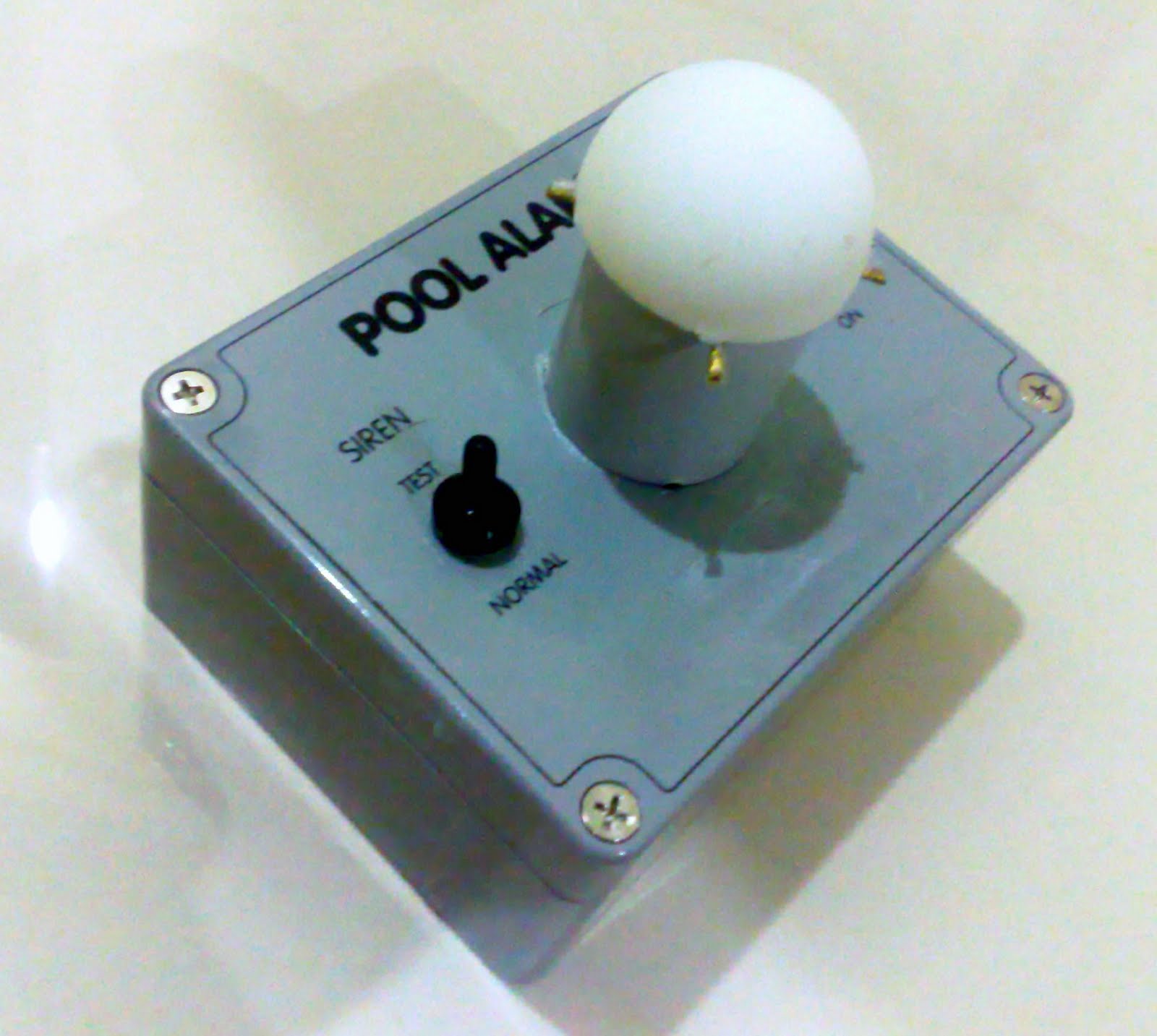
PROJECT SWIM-SA is based on this principle.


Being battery operated and enclosed in its own personalized waterproof case. Project SWIM-SA could be the solution for the problems faced. Inside a special sensor senses the rapid changes in the water level while filtering smaller insignificant input such as wind , rain , and not forgetting the swimming pools filter pump system. During which if these changes in the pools water level as would happen when someone falls in. On detecting this change, a siren sounds.


The device is designed to be placed into the pool where it would be left on all the time, except of course during which the pool is being occupied. Currently the idea is to have a built in waterproof on/off switch is provided to allow it to be removed from the pool without sounding. And another switch main purpose is to check whether the alarm is working at the same time checking whether the battery there is fully functioning and if the device it ready to operate.


Further discussion on the project takes place in improving the system .Planned additional features of the project would be installing a wireless radio frequency transmitter to the alarm allowing a secondary alarm to be placed in the house or another area where people could be notified of the event occurring.


Secondly another improvement to the alarm would be installing a failsafe system if ever it occurs when the alarm would be jeopardized by leaks to the alarm. This would be solved by the installation of a backup emergency system which would be able to function at the weakest of conditions and still complete on its task of saving a life.

Saturday, April 3, 2010

Objectives

The objectives of this final year project are :

1. To apply skills obtained throughout my diploma programme in this college.
2. To further gain experience in constructing a device at a small scale.
3. To master the skill of time management.
4. To be able to solve problems faced throughout the progress of the project effeiciently.
5. To learn new ways to design a circuit to meet demands of the device made.
6. To understand the capabilities of certain devices used in the process of the project.
7. To be more independent and resourceful.

Friday, April 2, 2010

Procedure

3.2.1 Choosing Project Title
 Project Swim-SA went through tedious thinking through before being selected as the title of my final year project. With advice from my supervisor, multiple sources has been surveyed and noted. Finally with the help of the Internet, an article was found to provide sufficient details which sparked interest on the topic of Pool Safety.

This article has provided me with the knowledge on the knowhow of the device which I thought of.

3.2.2 Approval by Supervisor
 After assuring the project title, my supervisor’s opinion was needed on my topic set. Whether it is deemed logical and based on my personal capability if that title is achievable by me. After a short discussion with my supervisor, my project title was confirmed which assured me that I can begin my full research on the topic.


3.2.3 Detailed Research on Project
 The following step on my project was to conduct a detailed research on the topics through various sources in my reach. Such sources include Books ,Magazines , Journals , The Internet, and Past recorded projects of seniors. The research on the project is to ensure that I as an individual posses the required information needed to construct this device.


3.2.4 Analysing the circuit of the project
 After completing the research at a given pace, the circuit for Project Swim-SA was obtained in two saperate parts which are , the Sensor Circuit and the Alarm Circuit.
Analyzing the circuit took place to clarify what is needed to make it work. Furthermore by analyzing the circuit, moderate modifications could take place to further improve the circuit’s capability and functionality.

Analyzing the circuit would help to develop knowledge on the construction of the circuit that could be used in the Oral Presentation and Poster Presentation.

The Circuit Maker Software was used to simulate and observe the circuit during functionality stage.


3.2.5 Purchasing Components.
 The availability of components were checked through local sites online along with sources abroad. Most of the basic components required in the construction of Project Swim-SA is available at several local markets except for the exceptional few which were the Low Powered 7555 IC and the Piezoelectric Transducer.

Locations of purchased products are stated below:-
Locally – Magnumtronic, Jalan Pasar.
Foreign – Dick Smith , Australia
Online – Amazon.com


3.2.6 Test of components on circuit board.

Figure 3.0 - Components Mounted on Bread Board.
 After components were purchased, the components were tested before construction begins. The circuit was tested on a standard bread board.


3.2.7 Troubleshooting
 Problems were analyzed and fixed to ensure the device works before placement on the PCB board could take place. Most of the problems faced is solved with the help of the lab assistant and my supervisor. If an error was detected the following steps were taken:-

1. Trace the source of the problem.
2. Attempt to determine the solution to the problem.
3. Conduct more research on the error at hand.
4. Seek supervisor or lab assistant for help.


3.2.8 Designing the PCB board

Figure 3.1 –PCB Board Design
 The design of the PCB board took place with a regular sketching. After obtaining a rough idea of how this would look like on a board, the circuit was then computed using the software called ExpressPCB.

The drawn diagram was printed on hard copy and sent to Gemsoft Sdn Bhd to conduct a stamp Etching process. With this process being conducted, multiple boards can be constructed in a quick time with a small fee.

The PCB board must be check upon completion to confirm that all noted points are in contact and if the board is in a sturdy condition.
With the completed board, the circuit is sanded to remove the unwanted copper layer and ink blots on the circuit board.


3.2.9 Designing of Acrylonitrile Butadiene Styrene Housing and Construction
(Acrylonitrile Butadine Styrene material is also known as ABS Plastic)

The material used to construct the housing of the device is designed to fit along with the PCB board. The construction material which is selected was the Acrylonitrile Butadiene Styrene. The company Gemsoft was able to provide the service of manufacturing several boxes to my specifications. Certain characteristics are given to the company which the box would be manufactured to match the required characteristics needed for the device.


Figure 3.2 – ABS Plastic Front Cover.


3.2.10 Soldering Components on PCB board.
 After completing the PCB construction, the next step is to mount all components onto the PCB board and which the soldering process could begin.

Figure 3.3 – Components Mounted on PCB Board.
 The soldering process takes time to master , which most students whom are not familiar to the technique. As most electronic components are heat sensitive, soldering should be a Touch-n-Go technique. After soldering each component, solders are checked to precision to ensure that it does not result in errors being made which would cause a short circuit between components.

Figure 3.4 – Soldering of Components on the PCB Board.


3.2.11 Testing the Completed Circuit Board
 After soldering all the electronic components on the PCB board, testing on the board is made to ensure that there is no short circuit present on the PCB board. A digital voltmeter is used to test the connections of the soldered components and the trace.


3.2.12 Writing and Submission of Reports.
A total of 4 reports are required to be submitted to the office . Those reports are stated below:-
1. Project Brief
2. 1st Progress Report
3. 2nd Progress Report
4. Final Project Report


3.2.13 Oral Presentation and Poster Presentation.
 For this project, it was a requirement to conduct an oral presentation on the project title. This presentation was based on the purpose to provide information on how the project is made and its circuit function, theory revelation, advantages and it’s core applications. Therefore all data collected along with the information present are compiled and presented in the form of a PowerPoint presentation.

Circuit Diagram


Circuit Analysis.

Based on Figure above, The signal from the piezo transducer is connected to the low pass filter, comprising IC1a and the associated resistors and capacitors. The 100kΩ resistors and 1µF capacitors set the low pass filter at 2.3Hz, while the 3.3MΩ feedback resistor and .015µF capacitor set the gain at 33 times at or below the 2.3Hz rolloff frequency.

IC1a is biased at ½ supply (+3V) at pin 3 by the 1MΩ voltage divider resistors connected across the supply. This half supply is decoupled with a 100µF capacitor.


The output of IC1a is also at ½ supply and this drives a 2.2kΩ resistor decoupled with a 470µF capacitor.

The voltage across the 470µF capacitor is therefore at 3V (½ supply) and the resistor and capacitor form a low pass filter to reject signals above 0.15Hz.


Hysteresis for the Schmitt trigger (IC1b) is set by the ratio of resistance between the 3V supply and pin 5 and the resistance between pins 5 and 7.

Thus the hysteresis can be varied from about 13mV when VR1 is wound with its wiper closes to the 2.2kΩ resistor and around 300mV when VR1’s wiper is closest to the 1MΩ resistor.
The output of the Schmitt trigger is used to drive a “charge pump” consisting of diodes D1 and D2 and capacitors C1 and C2.


These produce a voltage negative with respect to the +6V line across capacitor C2 whenever IC1b’s output is toggling (in example, the circuit is sensing water disturbance). The voltage across C2 is fed to pin 2, the trigger input of timer IC2.

IC2 is triggered when its pin 2 goes below one third of the supply voltage, or 2V. When triggered, the 47µF capacitor begins charging via the 1MΩ resistor and the pin 3 output goes high and drives transistor Q1’s base via the 2.2kΩ resistor. This transistor drives the siren.

The siren can be driven directly via the 6V supply or via the 10kΩ resistor connecting to the 6V supply for a reduced output level (for testing). This is selected using switch S2.

The output of IC2 (pin 3) stays high until the 47µF capacitor at pin 6 reaches two thirds of the supply voltage. The pin 3 output then goes low and the capacitor is discharged via the pin 7 output and 10kΩ resistor. The time duration for the alarm is around 50 seconds.


When power is first switched on, the reset input of IC2, pin 4, is held low via the 10µF capacitor to prevent the timer from being triggered by IC1b.

After about a second the reset pin voltages reaches about 1V due to the 10µF capacitor being charged via the 560kΩ resistor and then the timer can be triggered.

Thursday, April 1, 2010

Block Diagram


Analysis of the Block Diagram

The block diagram of Project SWIM-SA is shown on the previous page. The sensor itself consists of a piezo element which supports a weight. As the piezo element is attached to a floating box which floats on the swimming pool surface. Any upwards-movement of water will cause the floating box to rise, pushing against the piezo which doesn’t move as quickly due to the inertia of the attached weight. When this occurs, the piezo element generates a small voltage output.

The piezo element is the main component of the swimming pool alarm as its function depends on its ability to detect the movement.

With research done on several textbooks it is fully confirmed that a downward movement of the box will not usually cause decompression of the element. This is because the floating box drops with the gravity at the same rate as the mass.

The signal from the piezo detector is amplified by IC1a and filtered so that only frequencies below about 2Hz pass through. The amplifier has a gain of 33 for frequencies below 2Hz.
As the mass on the piezo element also damps out any fast movement (again due to inertia), it reduces the high frequency response of the piezo element. Thus the output from the filter only changes for slower movements.


The signal is squared up by the following Schmitt trigger (IC1b) and has an adjustable threshold to allow setting the sensitivity to pool movement.

The Schmitt trigger output is a low frequency square wave which changes with the piezo detector output. The signal drives a charge pump which requires at least two pulses from the Schmitt trigger before the output from the charge pump is low enough to trigger the following timer. This requirement before triggering the timer reduces the likelihood of false alarms.
The timer produces a high signal for about 50 seconds which drives the siren driver (Q1) and siren. The siren should be sufficiently loud to attract attention.

The circuit is housed in a sealed box to prevent water getting in. However, the siren must be exposed to the outside air so that it can be heard. It also needs to be made as loud as possible to attract attention.

By feeding the siren into a tuned port would help increase the amplitude of the siren generated. This port would be covered to prevent the device from getting wet.

After referring to some calculations actual dimensions of the port and cover has been designed to look like a light house as based on theory this design would help amplify the sound as it reaches the air as sound is channeled through a small tunnel will maximize the sound output level.

Searching for parts being in the device for the tower for the siren is quite hard as parts are unique. But fortunately an alternative has been determined as several scrap parts of other devices such as the flange port of a light bulb and a ping-pong ball could be used. This should provide the same equivalent characteristics needed to improve the alarm.

Wednesday, March 31, 2010

Statistics


Based on statistics obtained, the chart above was tabulated. With constant research on my project has driven me to further improve on my designs of the project. Most of the statistics are as below:-


• In 2004, there were 3,308 unintentional drowning in the United States, an average of nine people per day.

• It is estimated that for each drowning death, there are 1 to 4 nonfatal submersions serious enough to result in hospitalization. Children who still require cardiopulmonary resuscitation (CPR) at the time they arrive at the emergency department have a poor prognosis, with at least half of survivors suffering significant neurologic impairment.
• 19% of drowning deaths involving children occur in public pools with certified lifeguards present.

• A swimming pool is 14 times more likely than a motor vehicle to be involved in the death of a child age 4 and under.

• Children under five and adolescents between the ages of 15-24 have the highest drowning rates.

• Of all preschoolers who drown, 70 percent are in the care of one or both parents at the time of the drowning and 75 percent are missing from sight for five minutes or less.

• The majority of children who survive (92 percent) are discovered within two minutes following submersion, and most children who die (86 percent) are found after 10 minutes. Nearly all who require cardiopulmonary resuscitation (CPR) die or are left with severe brain injury.

Research

The project has been completed with the help of sources indicated below during my research period. All necessary information which has been collected are stated below:-

1. http://www.safetyalarms.com/
 This website has provided me the idea of designing Project Swim-SA. Furthermore , this page shows detailed analysis of products used in the prevention of drowning kids.


2. http://www.sonarguard.com/#
 This page given me ideas on how to modify my circuit with a much more sustainable alarm system.


3. http://www.jclahr.com/science/psn/zero/winding/gravity_sensor.html
 The sensor in this page, provided the basic knowledge of allowing me to attempt to use a sensor which could be able to detect the changes in water level motion.


4. http://www.electronics-manufacturers.com/products/sensors-transducers-detectors/piezoelectric-transducer/
 From this site I manage to obtain knowledge on the workings of a piezoelectric transducer and using it to replace the original gravity sensor which was initially being applied to the circuit.


5. http://www.ndted.org/EducationResources/CommunityCollege/Ultrasonics/EquipmentTrans/piezotransducers.htm
 The information present in this webpage gave me the knowledge on how i could use the piezoelectric transducer to produce the output wanted in my circuit.


6. http://home.cogeco.ca/~rpaisley4/LM7555.html#30
 The timer based IC-circuit that is the parts of my project circuit, this page shows the simple configuration that I needed to construct my IC7555 on.

Sunday, March 28, 2010

Discussion

The main component of Project Swim-SA is the Piezoelectric Transducer which supports a weight. In the scenario of the box oscillating up and down , this motion will cause the weight attached to the transducer to push against the plate. When this occurs, the piezo element generates a small voltage output.

The piezo element is the main component of the swimming pool alarm as its function depends on its ability to detect the movement.

The signal from the piezo detector is amplified by IC1a and filtered so that only frequencies below about 2Hz pass through.

The output from the filter only changes for slower movements.

The signal is squared up by the following Schmitt trigger (IC1b) and has an adjustable threshold to allow setting the sensitivity to pool movement.

The Schmitt trigger output is a low frequency square wave which changes with the piezo detector output. The signal drives a charge pump which requires at least two pulses from the Schmitt trigger before the output from the charge pump is low enough to trigger the following timer. This requirement before triggering the timer reduces the likelihood of false alarms.
The timer produces a high signal for about 50 seconds which drives the siren driver (Q1) and siren. The siren should be sufficiently loud to attract attention.


The circuit is housed in a sealed box to prevent water getting in.

However, the siren is exposed to the outside air so that it can be heard. It has also been designed to be as loud as possible to attract attention.

After referring to some calculations, the cover has been designed to look like a light house as based on theory this design would help amplify the sound as it reaches the air as sound is channelled through a small tunnel will maximize the sound output level.

The user is only required to switch on the device and place it at the source which he/she would be monitoring. (Source = Swimming Pool)

Saturday, March 27, 2010

Conclusion

In conclusion, Project Swim-SA is a simple designed device which is also very effective at what it does.

The main objective of Project Swim-SA is to save lives and with this greatly reduce the drowning rates in the world. As drowning rates in the world has always been a large problem which the community face, this device is the solution to the problems.

With the technology present in this device will give us a chance to further improve our lifestyle towards modern technology. In this report it was also described that the Piezoelectric Transducer is capable of generating voltages at a low level, but imagine the feats which could be acco\\mplished when this device is largely produced for the generation of our power sources in the world.

Through the works of the Project, I’m certain that I have gained a vast amount of knowledge and experience which would benefit me in my coming years of education.

Finally, I would like to again thank everyone whom has been a great help to me in many ways throughout the process of my final project. Not forgetting Mr. Dennis Koh Mui Siang whom played a major role providing me with guidance and perseverance which led to the success of my project.

Saturday, March 20, 2010

Project Progress Summary

8.1 Project Reports
• Project Synopsis
• Project Brief
• 1st Progress Report
• 2nd Progress Report
• Final Project Report


8.2 Construction of the Project
• Choosing Project Title
• Approval by Supervisor
• Detailed Research on Project
• Analysing the circuit of the project
• Purchasing Components.
• Test of components on circuit board.
• Troubleshooting
• Designing the PCB board
• Designing of Acrylonitrile Butadiene Styrene Housing and Construction
• Soldering Components on PCB board.
• Testing the Completed Circuit Board
• Writing and Submission of Reports.
• Oral Presentation and Poster Presentation.
• Data Recording


8.3 Research and Presentation
• Research on the project title
• Research on the circuit of the project
• The study of the components which would be used for the project
• Preparation of PowerPoint slides for oral presentation
• Research on Circuit Operation
• Gathering of Information for Poster Presentation.
• Designing the poster and the summary

Friday, March 19, 2010

Gaant Chart

Click Image to Enlarge.

Wednesday, March 17, 2010

References

The circuit idea was obtained from an online webpage called “Silicon Chip”
Following is the list of electronic reference books which are fundamental to my circuit components and operation;

1) Low Voltage Wiring: Security/Fire Alarm Systems ,Terry Kenedy , 1996,Mc Graw-Hill
2) Intruder Alarms , Gerard Honey , Mc Graw Hill
3) Modern Control Engineering , Ogata Katsuhiko , Prentice Hall.
4) Digital Logic State Machine Design Third Edition by David J.Comer, Saunders College Publishing, 1995.
5) Management of Knowledge in Project Environments , Patrick Fong , Prentice Hall
6) Swimming Pool Inspection, Safety, Maintenance , Show Me How Videos
7) Electrical & Electronic Technology Eighth Edition by I Mckenzie Smith with John Hiley and Keith Brown, Prentice Hall 2002.
8) Power Electronics by Marvin J.Fisher, PWS-Kent Publishing Company, 1991.
9) Electronic Devices and Circuit Theory Eighth Edition International Edition by Robert L.Boylestad and Louis Nashelsky, Prentice Hall, 2002.
10) Digital Fundamentals Eighth Edition International Edition by Thomas L.Floyd, Prentice Hall, 2003.
11) Modern Control Systems by Nise Norman,Cummings Publishing Co.

To obtain data sheets for the ICs and components that was used in my circuit, I have browsed the following websites;

1) http://datasheetcatalogue.com
2) http://www.rsmalaysia.com
3) http://www.farnell.com
4) http://focus.ti.com/docs/prod/folders/print/tl062.html
5) http://www.chipdocs.com/datasheets/datasheet-pdf/SGSThomson-Microelectronics/TL062.html
6) http://www.edaboard.com/ftopic327824.html
7) http://www.fairchildsemi.com
8) http://www.hobbyengineering.com
9) http://everything2.com/title/555+Timer
10) http://www.semtech.co.uk
11) http://www.eztechsystems.com
12) http://www.linxtechnologies.com/
13) http://www.mistersoft.org/freelancing/getafreelancer/2009/06/Electronics-Wireless-Simple-transmitter-and-reciever-schematic-446072.html
14) http://www.epanorama.net/wwwboard/messages/8300.html
15) http://www.play-hookey.com/digital/experiments/rtl_schmitt.html
16) http://www.electronics-tutorials.com/filters/low-pass-filters.htm
17) http://www.safetyalarms.com/
18) http://www.sonarguard.com/#
19) http://www.jclahr.com/science/psn/zero/winding/gravity_sensor.html
20) http://www.electronics-manufacturers.com/products/sensors-transducers-detectors/piezoelectric-transducer/
21) http://www.ndted.org/EducationResources/CommunityCollege/Ultrasonics/EquipmentTrans/piezotransducers.htm
22) http://home.cogeco.ca/~rpaisley4/LM7555.html#30